Wavecontrol
Wavecontrol is an engineering company, founded in 1997 and specialising in the measurement of electromagnetic fields.
With a clearly international calling, our company has headquarters in Europe (Barcelona, Spain) and the United States (New Jersey).
Our network of distributors operates in over 50 countries on five continents, and we have implemented ISO 9001 and ISO 17025 quality control systems for the ongoing improvement of processes, products and services.
What We Do
- We are driven by enthusiasm for the development of innovative technological products;
- Eagerness to work with and help customers around the world;
- Commitment to the quality of something well done;
- And a clear desire to contribute to people’s health and safety.
Safety in Electromagnetic Fields: RF Safety EMF Safety
With over 26 years’ experience, we design and develop professional instruments for measurement, monitoring and evaluation of human exposure to electromagnetic fields.
Our calibration laboratory (LabCal Wavecontrol) is ENAC accredited and recognised in most countries around the world through the ILAC network. All devices manufactured by Wavecontrol are delivered standard with ISO 17025 accredited individual calibration at no extra cost, as a further indication of our commitment to quality and reliable measurement.
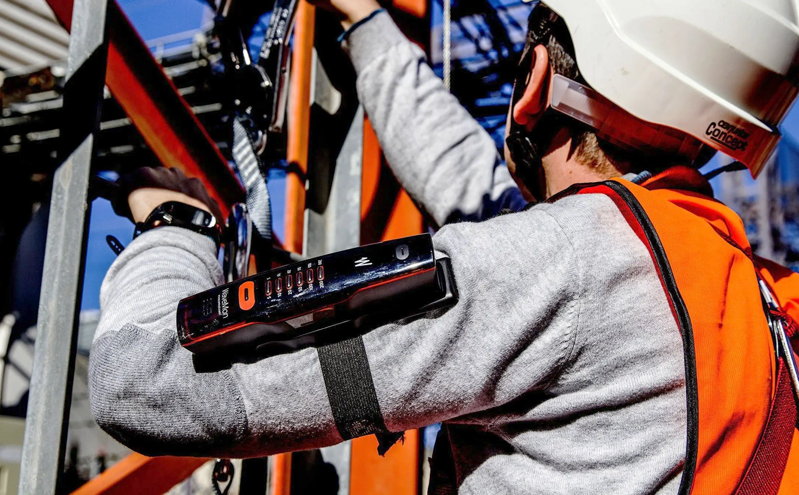
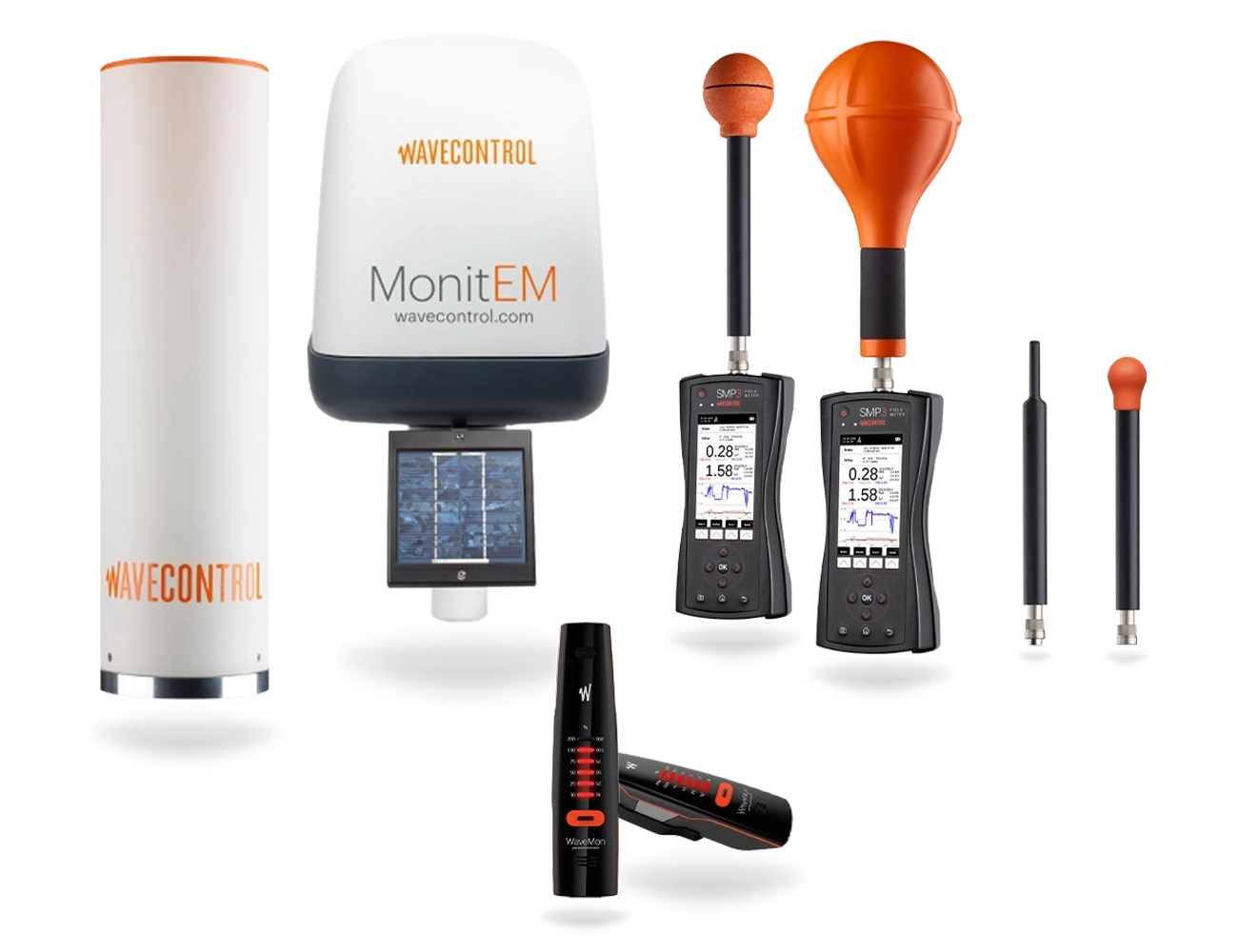
Since we have our own R&D department, we seek the most innovative solutions for our customers. In this sense, we are proud to offer the WaveMon, a personal monitor which incorporates all necessary functionalities for a correct and effective surveillance of electromagnetic fields exposure.
Additionally, the SMP3 device, the most versatile and innovative field measurement device on the market, along with the MonitEM family of devices and the MonitEM-Lab version, all of which have special characteristics that make them unique. Likewise, our R&D department can respond to special needs.
Do not hesitate to ask.
Global R&D
We strongly believe in R&D and are committed to the continuous development of high-quality professional products. Our R&D projects are supported by the European Union and other international bodies. The Centre for the Development of Industrial Technology (CDTI) and the European Union ERDF funds have financed the ONIRIS project (Optimised Analysis for Non-Ionising Radiation). This project has been carried out in Barcelona between May 2015 and August 2019, with a total budget of 713,769.00 euros.
Upcoming Events
Frequently Asked Questions on EMF
General Questions
What sort of instruments does Wavecontrol produce?
Wavecontrol produces professional quality instruments for measuring electromagnetic fields for radio safety applications, i.e. evaluation and control of exposure of workers and people in general to electromagnetic fields.
What services does Wavecontrol offer?
Wavecontrol offers advice on the suitable equipment for each application, regulation, law or recommendation concerning exposure to electromagnetic fields. Wavecontrol’s offer of after-sales service includes repairs and ENAC/ILAC certified ISO 17025 calibrations. We are committed to quick response, efficacy, quality and competitive prices. We also offer in-person and webinar training and courses.
What is “Electromagnetic Safety” or “EM Safety”?
Electromagnetic Safety or EM Safety refers to the exposure of people to electromagnetic fields, which must be kept below certain limits specified by law, regulations and domestic and international recommendations in that regard.
What is “Radio Frequency Safety” or “RF Safety”?
“Radio Frequency Safety” or “RF Safety” refers to the exposure of people to radio frequency electromagnetic fields, which must be kept below certain limits specified by law, regulations and domestic and international recommendations in that regard. This normally concerns fields with frequencies between 3 Hz and 300 GHz.
What is non-ionising radiation (NIR)?
Non-ionising radiation refers to any type of electromagnetic radiation that does not carry enough energy per quantum (photon energy) to ionize atoms or molecules, that is, to completely remove an electron from an atom or molecule. It includes electric and magnetic fields, radio waves, microwaves, infrared, ultraviolet, and visible radiation.
What is Wavecontrol LabCal?
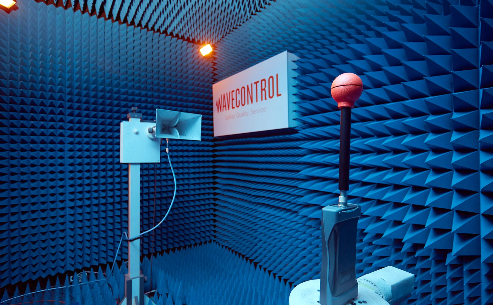
Wavecontrol LabCal is Wavecontrol’s calibration laboratory. All equipment manufactured by Wavecontrol is subjected to individual ISO/IEC 17025 certified calibration as part of the quality control process for each instrument. This is a standard operating procedure and does not involve any extra cost for the equipment. Wavecontrol LabCal is equipped with an anechoic chamber, TEM test cell, positioners, antennas, RF and low-frequency amplifiers, signal generators, watt meters, parallel plates, Helmholtz antennas, and many more instruments for calibrating field probes between 1 Hz and 18 GHz.
What is ENAC/ILAC accredited ISO/IEC 17025 calibration?
This means that the calibration has been performed by a certified laboratory with certified personnel and procedures. Many countries have an official organization to certify laboratories for testing or calibration. Some examples are A2LA (US), CNAS (China), DAkkS (Germany), UKAS (UK), COFRAC (France), OAA (Argentina), CGCRE (Brazil), TUNAC (Tunisia), ISRAC (Israel), NABL (India), etc. That organization in Spain is ENAC, the Entidad Nacional de Acreditación, which is responsible for certifying laboratories. LabCal Wavecontrol is an ENAC certified calibration laboratory, which guarantees that its personnel are qualified, that it uses optimal criteria and procedures, and that it can produce accurate calibration figures. This link will show you the countries that are parties to the conventions so that you may check whether Wavecontrol calibrations are also official in your country: ILAC.
What is the difference between accredited ISO 17025 and ISO 9001 calibration?
Some calibration reports present themselves as ISO 9001, which is misleading. There is no such thing as an “ISO 9001 calibration”. A calibration laboratory can only be ISO 17025 certified, as that is the standard concerning measurement laboratories. ISO 9001 is a general quality standard for enterprises. The fact that an enterprise is ISO 9001 certified does not in any way mean that its laboratory is ISO 17025 certified, i.e. its calibration facilities, personnel and procedures are not certified. Wavecontrol is an ISO 9001 certified enterprise and furthermore its laboratory is ISO 17025 certified, and it can therefore issue calibration certificates recognised by ENAC and internationally valid with the ILAC seal of approval.
What is ICNIRP?
ICNIRP is the acronym for the International Commission on Non-ionising Radiation Protection. As an independent organization, the International Commission on Non-Ionizing Radiation Protection (ICNIRP) provides scientific advice and guidance on the health and environmental effects of non-ionizing radiation (NIR) to protect people and the environment from detrimental NIR exposure. ICNIRP gives recommendations on limiting exposure for the frequencies in the different NIR subgroups. It develops and publishes Guidelines, Statements, and reviews used by regional, national, and international radiation protection bodies, such as the World Health Organization.
What are CENELEC, IEC and IEEE?
CENELEC is the acronym for the European Committee for Electrotechnical Standardisation, the organisation responsible for developing standards for the European Union. Its publications are the standards whose titles begin with the initials EN. IEEE is the acronym for the Institute of Electric and Electronic Engineers. Although it has its headquarters in the United States, it has members around the world. It develops standards that are applied in the US and other countries. IEC is the acronym for the International Electrotechnical Commission, which, like the two preceding organisations, develops technical standards, although at the international level. Those three organisations work wherever possible to harmonise their different standards and so facilitate their application around the world.
What is the European Directive 2013/35/EU?
European Directive 2013/35/EU is the new directive on worker safety and electromagnetic fields. It leads the world in protection in the workplace against a physical phenomenon that is increasingly present in people’s lives and jobs. It addresses all jobs, regardless of industry or activity, and it provides as the salient factors for:
- Maximum values for exposure and levels of action;
- Employers’ obligations;
- It was published in 2013 and must be transposed to EU Member States’ domestic law by July 2016.
The title of the Directive is as follows: “DIRECTIVE 2013/35/EU of the European Parliament And Of The Council of 26 June 2013on the minimum health and safety requirements regarding the exposure of workers to the risks arising from physical agents (electromagnetic fields) (20th individual Directive within the meaning of Article 16(1) of Directive 89/391/EEC) and repealing Directive 2004/40/EC”.
How can telecommunication base stations be certified?
This will depend on the applicable domestic law, but in most cases use of professional broadband measurement equipment is sufficient. The typical configurations include:
- SMP3 + WPF3;
- SMP3 + WPF6;
- SMP3 + WPF8;
- SMP3 + WPF18.
A tripod must be used so that the measurements can be taken without the user being present. In some cases, 6-minute sliding window averages and spatial averages must also be taken. This is possible with any SMP3 combination, in keeping with ICNIRP guidelines. The SMP3 complies with the EN 50492 and IEC 62232-1 standards, among others, making it ideal for this application. The measurement data can be downloaded to a PC with USB connection by means of a complete software package that allows you to:
- Control the device;
- Display, position and manage data and screenshots;
- Upload data to an Internet server;
- Generate complete visual reports of measurements.
How can I measure exposure to low frequency E and H fields?
At high frequencies, we normally find ourselves in far-field conditions. Under those conditions, the relationship between the electric field (E) and the magnetic field (H) is direct and constant, and so we only need to measure one of those values. At low frequencies, we often find ourselves in near-field conditions. In this case, we need to measure the electric field and the magnetic field separately. The SMP3+WP400 combination is ideal for such conditions, since the WP400 probe measures both the E and H fields. It also allows both simple and comprehensive measurements by means of:
- Broadband measurements;
- Frequency analysis by means of real-time FFT;
- Special peak detection function;
- Changes in specific frequency over time;
- Real-time application of the Weighted Peak Method specified by ICNIRP and IEC/EN 62233.
SMP3
What does broadband measurement mean?
It means that the result obtained, e.g. 3 V/m in the case of an E field probe, is the result of including all the energy falling within the probe’s measurement range, i.e. if we use a WPF8 probe (100 kHz – 8 GHz), the result is the total NIR exposure within that range.
What does “real-time FFT-based” spectral analysis mean?
It means that the device carries out FFT by means of continuous digital processing, so that it can analyse signals and their variation over time with no information loss. FFT spectral analysis produces an output similar to that of a spectrum analyser, although with certain important differences. A spectrum analyser uses analog mixing and filtering to classify the components of the signal into a continuous frequency plot. It is an analog, nonreal-time method, since it sweeps through the band of interest and that process goes on for given time, meaning that it cannot properly track a signal that varies over time. FFT spectral analysis captures the whole signal instantly. If samples are taken at a rate of twice the highest frequency (according to the Nyquist criterion), the signal can be captured with no information loss. This is accomplished with digital processing. With correct overlap processing of successive FFTs, even very short, low-amplitude events can be detected. This ability to detect very brief signals is very useful in industrial processes where signals are not continuous but instead highly variable, with brief peaks.
What is the “Weighted Peak Method”?
The Weighted Peak Method is a measurement method defined by ICNIRP that allows easy real-time evaluation of compliance with limits. Some standards, such as IEC 62311, refer to this method as Time Domain Assessment. It takes into account the full frequency range (1 Hz – 400 kHz) and presents the output as a percentage (%) of the limit, weighting the results (for peak values and RMS) on the selected limit curve, automatically applying the different limits depending on the frequency. In short you do not need to do anything; the device makes all the calculations for you.
Why should I use the “Weighted Peak Method”?
ICNIRP and European Directive 2013/35/EU define limits for exposure to low-frequency electromagnetic fields. Those exposure limits are peak values over time. In the case of sinusoidal fields, those peak values are equal to the root mean square (RMS) values multiplied by the square root of 2. In the case of non-sinusoidal fields, both ICNIRP and European Directive 2013/35/EU specify that measurement of exposure must be based on the weighted peak method.
What does the “Weighted Peak Method” consist of?
The Weighted Peak Method is used for coherent non-sinusoidal signals, which may consist of distorted sinusoidal cycles or a series of non-sinusoidal pulses. In those cases, the resulting spectrum is made up of substantial harmonic components over a broad bandwidth and the waveform can show value peaks that are much higher than the RMS value. In such cases, the method of adding up the different frequency components is not suitable because, if the phase information is not taken into account, the results obtained may be too conservative (excessive overestimates). The Weighted Peak Method determines the relationship to the reference exposure level by multiplying the complex frequency components of the time derivative (dB/dt) by a complex weighting function depending on the frequency and relating to the phase. The SMP3+WP400 combination does this in real time by means of digital processing in the time domain, simultaneously for the three orthogonal field sensors making up the WP400 probe.
Which standards does the SMP3 comply with?
The SMP3 complies with all standards for measurement of people’s exposure to electromagnetic fields, including: ICNIRP Guidelines, IEC 61786-1, IEC 6251237, IEC 62311, IEC 62369, IEC 60601, IEC 62369-1, IEC 62110, IEC 62233, EN 50400, EN 50401, EN 50499, EN 50496, EN 50554, EN 50475, EN 50476, EN 50492, EN 50413, EN 50519, EN 50444, EN 50505, EN 50500, ECC recommendation 02(04), IEEE Std 644™-1994 (R2008), IEEE Std C95.1™-2005, IEEE Std C95.1a™-2010, IEEE Std C95.6™-2002 (R2007), etc.
Can the SMP3 detect and measure peaks?
Yes, it can, thanks to its high-speed digital processing that ensures the ability to detect peaks of up to 1 µs. It can also detect isolated very high amplitude peaks thanks to a special self-scaling function that adapts the device’s dynamic margin (amplification) to the necessary levels.
Why is the sliding window average function important?
ICNIRP, as well as most exposure standards, calls for averaging of measurements over time, normally within any 6-minute window or period. If we want to evaluate all the 6-minute averages, that window needs to be a sliding window, following the rule “new sample – new average”. This technique is mentioned specifically in IEEE C95.3, ITU-T K.83, etc. When a new sample is taken, the oldest sample is eliminated and a new average is calculated, so that the result of each average can be compared with the exposure limit. The diagram below shows that the averages for period 1 and period 2 are lower than an average of 6 intermediate samples, so if we want to measure the worst case, i.e. the highest result, we need to use the sliding window technique.
What is the purpose of the spatial average function?
Some exposure standards call for measurements taken from different points and then averaged, which is referred to as the spatial average. For example, measurements may be taken at a given place at three different heights, i.e. 1.1 m, 1.5 m and 1.7 m. A measurement is taken at each of those heights and the final result will be the average of the three. The SMP3 has a function that allows this to be done automatically, not just from three points but from as many as may be necessary.
What does RMS mean and why is it important?
The RMS value is the root mean square value of a signal that varies over time. For an alternating current signal it would be equivalent to the direct current that would produce the same power dissipation in a given load. The effective value gives us an average of the power of a signal, which is the most important factor in most cases. ICNIRP, CENELEC, IEC and IEEE all call for measurements of effective value or RMS.
How is the “print screen” function of the SMP3 used and why?
The SMP3 has a dedicated button for a screenshot of the device at any time. The screenshot is saved to memory whether a measurement is being made or not. All saved screenshots are accessible when consulting the data of the device, whether from the SMP3 itself or from the PC software. This is very useful for reports, giving them a very visual and up-to-date appearance. It is also useful for one-click saving of informal measurement data.
Is there PC software for the SMP3, and how can I use it?
Yes, the SMP3 is equipped with extraordinary PC software that allows you to:
- Download and display data as lists, tables or dynamic diagrams;
- Position measurements using Google Maps;
- Create reports including screenshots;
- Update firmware;
- Upload data to an Internet control centre;
- Control the device remotely.
This tool is highly appreciated by users who have to create high-quality reports quickly.
Do I need to connect to an external GPS?
You do not need to connect to any external GPS because the SMP3 is equipped with a high-performance GPS that the user can switch on or off as they wish.
What is “time measurement for a given frequency”?
This is a function that allows use of the real-time spectral analysis to set the frequency analysis at a given frequency and see its variation over time. This useful if we want to analyse a given frequency and its behaviour.
Do I need one probe for the H field and another for the E field for low frequency (1 Hz – 400 kHz) measurements?
No. The WP400 probe can measure both the electric field and the magnetic field, so you do not need to change the probe to measure both fields. This means lower cost and less time to take both measurements.
How connective is the SMP3?
The SMP3 can be connected by USB or fibre optics for remote control. Fibre optics can be used for laboratory applications or to avoid unwanted feedback; an F.O. to USB adapter is supplied. The USB connection is normally used for downloading data, creating reports, updating firmware, etc.
What is the web Control Centre?
The web or Internet Control Centre is a server running Wavecontrol software in a LAMP (Linux-Apache-MySQL-PHP) environment. It is delivered ready for Internet connection, to receive data from MonitEM or SMP3 devices and to post data on the Internet via a specific web page.
Its two main functions are:
- To operate as a control centre for the equipment, managing additions and removals, parameterisation, data reception, configuration, etc;
- To deliver and post data on the Internet via a dedicated web page that the user can include on their own web page.
MonitEM
How is MonitEM powered?
MonitEM devices are equipped with the “Smart Energy” system that allows them to run smoothly on AC, solar power, or both. If both systems are used, the system is smart enough to use AC power only when necessary, optimising energy efficiency and sustainability.
What is IP 66?
The international standard IEC 60529 defines IP (Ingress Protection) codes, a system for classifying degrees of environmental protection provided by the casings of electric or electronic equipment. The code is made up of two numbers: the first refers to protection against ingress of solid particles, and the second refers to ingress of water. In the case of solid particles, 6 is the highest rating (“no ingress of dust under any circumstance”). In the case of ingress of water, 6 means that the equipment is protected against “very powerful water jets”. Level 7 then refers to “complete immersion in water”. MonitEM devices have a protection level of IP66, the highest for its class and suitable for equipment that has to work permanently outdoors.
How is data sent to the Control Centre?
MonitEM devices communicate with the control centre by IP (Internet Protocol) via a built-in GPRS/3G modem. IP communication means that all those devices can send data simultaneously at any time.
What is the web Control Centre?
The web or Internet Control Centre is a server running Wavecontrol software in a LAMP (Linux-Apache-MySQL-PHP) environment. It is delivered ready for Internet connection, to receive data from MonitEM or SMP3 devices and to post data on the Internet via a specific web page.
Its two main functions are:
- To operate as a control centre for the equipment, managing additions and removals, parameterisation, data reception, configuration, etc;
- To deliver and post data on the Internet via a dedicated web page that the user can include on their own web page.
How long can a solar-powered device work with no sunlight?
MonitEM devices are low power consumption so they can usually work without sunlight for over 13 days straight.
If a MonitEM device cannot communicate with the control centre, how long can it store data with no information loss?
MonitEM have a very large built-in storage capacity and they can store all information locally for years.
Can a MonitEM device work without a control centre?
Yes. You can program the device to store all its data internally. When you want to consult the data, you can download them locally to a PC via a USB connection.
Where are MonitEM devices usually installed?
You can take two basic approaches:
- Install the device near the antenna or transmitter, in the direction and position where the highest level is expected according to its radiation pattern. In this case, you will be installing the device at the maximum exposure point (worst case), so all other points or places in other directions or farther away from the antenna will have lower levels than the monitored level;
- Install the device at the exact place (sensitive point) where levels of exposure electromagnetic fields need to be monitored, i.e. a specific building, school, day care centre, hospital, workplace, etc.
What is Recommendation ITU-T K.83?
Recommendation ITU-T K.83 “Monitoring of Electromagnetic Fields” is a recommendation issued by the International Telecommunication Union on monitoring electromagnetic fields in connection with personal safety. The summary of the Recommendation ITU-T K.83 states as follows: “Recommendation ITU-T K.83 gives guidance on how to make long-term measurements for the monitoring of electromagnetic fields (EMF) in the selected areas that are under public concern, in order to show that EMFs are under control and under the limits. The purpose of this Recommendation is to provide for the general public clear and easily available data concerning electromagnetic field levels in the form of results of continuous measurement”. MonitEM devices comply with Recommendation ITU-T K.83.
Why is the sliding window average function important?
ICNIRP, as well as most exposure standards, calls for averaging of measurements over time, normally within any 6-minute window or period. If we want to evaluate all the 6-minute averages, that window needs to be a sliding window, following the rule “new sample – new average”. This technique is mentioned specifically in IEEE C95.3, ITU-T K.83, etc. When a new sample is taken, the oldest sample is eliminated and a new average is calculated, so that the result of each average can be compared with the exposure limit. The diagram below shows that the averages for period 1 and period 2 are lower than an average of 6 intermediate samples, so if we want to measure the worst case, i.e. the highest result, we need to use the sliding window technique.
Is there any danger of collision or data saturation if a system includes many MonitEM devices?
No, because the devices transmit their data over the Internet using an IP protocol, so they can send their data, even all at once, and the server will receive the data with no difficulty.
Field Probes
What is an isotropic probe?
An isotropic probe is one that measures electromagnetic radiation arriving from anywhere in space. The result does not depend on the direction of the electromagnetic field or its position. The isotropicity is not perfect, however, since response is not identical for all spatial directions. This is known as isotropy error, normally defined as ± x dB, which should be stated on the technical data sheet. The lower the figure, the smaller the measurement error.
What does RMS mean and why is it important?
The RMS value is the root mean square value of a signal that varies over time. For an alternating current signal it would be equivalent to the direct current that would produce the same power dissipation in a given load. The effective value gives us an average of the power of a signal, which is the most important factor in most cases. ICNIRP, CENELEC, IEC and IEEE all call for measurements of effective value or RMS.
What is a broadband probe and why is it useful?
A broadband probe is one that measures across its full working frequency band at once.
It is useful because:
- Measurement is fast and easy;
- The result obtained directly shows the total exposure level, with no additional calculations needed;
- Results are easy to interpret and communicate;
- Broadband devices are less expensive.
What is automatic probe recognition?
This is a built-in function of the SMP3 and MonitEM that detects and recognises a probe automatically when it is connected. The type, model and serial number of the probe is shown on the screen and in the output. You do not have to switch the device off to change the probe: you can disconnect the current probe and connect a new one, and the device will recognise and continue working with the new probe.
What is flat frequency response?
Field probes with flat frequency response show the same response across their full frequency range. This means that they measure fields of any frequency in the same way. The flatness is not perfect, however, since response is not identical for all frequencies, and this should be stated on the technical data sheet. It is normally stated as “frequency response” or “flatness” and defined as ± x dB deviation. The lower the figure, the smaller the measurement error.
Why is it important for a field probe to be very linear?
Linearity is a characteristic that defines the response of the probe to different field levels. A probe should be equally responsive to all levels within its measurement range, i.e. we want the probe to respond the same to 0.5 V/m as to 100 V/m. If the response of the probe is not linear, it will measure some levels well but it will be substantially off at other levels. Linearity is not a perfect characteristic, and this should be stated on the technical data sheet for each probe, defined as ± x dB deviation. The lower the figure, the smaller the measurement error.
What is probe sensitivity?
Probe sensitivity is defined as the lowest value that it can measure. This should be stated on the technical data sheet.
What does “temperature response” mean?
The temperature response of a field probe is one of the factors that we find on its technical data sheet. It refers to the different response of the probe at different temperatures. The response to a given field will not be exactly the same when measured at -10°C as at 40°C, and that difference needs to be shown correctly. It is normally defined as variation in dB per degree of temperature (x dB/°C) related to a reference temperature.
What is attenuation at 50/60 Hz and why is it important?
Wavecontrol broadband high frequency probes have a very high attenuation, of 80 dB, at 50/60 Hz.
This is very important because they are often used in situations where 50/60 Hz electric and magnetic fields are present, since that is frequency of power grids. If you do not use a probe with that degree of attenuation, your results will be masked or affected by those fields, producing incorrect values.
